Einleitung
This guide teaches you how to replace the motherboard in an HP EliteBook 8560w.
-
-
With the back of the laptop facing towards you, simply push the battery latch to the right, and out comes the battery.
-
-
-
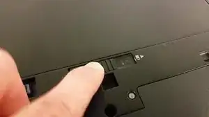
Push the latch to the left like shown in the video, and then help the bottom cover off, like in the attached video.
-
-
-
Get out the Philips #1 bit, and unscrew the three captive screws securing the keyboard.
-
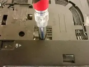
Remove the single captive Philips screw securing the disc drive, then push the disc drive out by using your screwdriver on the area right above the disc drive screw.
-
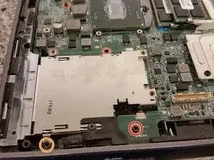
Remove the two captive Philips screws securing the Smart Card (SC) reader, then lift the SC reader up. The SC reader is hinged at the point opposite to the screws.
-
-
-
With the laptop's screen open and the disc drive out, hold up the laptop, push on the underside of the metal plate below the keyboard.
-
Flip the laptop right side-up and pull the keyboard, taking care not to rip the ribbon cables out of their sockets.
-
Disengage the ribbon cables from their sockets by pulling up on each socket tab, then pulling the cable gently upwards.
-
-
-
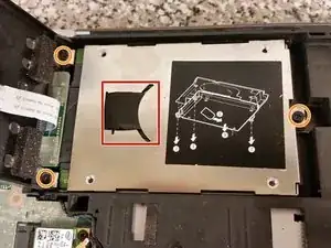
Use your fingers or a screwdriver to get under the black pull tab for the hard drive, and pull it out from the curved hole it is under.
-
Remove the three captive Philips screws securing the hard drive caddy.
-
-
-
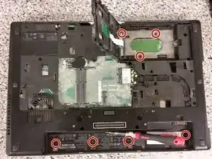
Break out the Torx T9 bit, and start removing the seven M2.5x3 screws securing the palmrest.
-
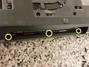
Remove the three M2x4.5 screws under where the optical drive was.
-
-
-
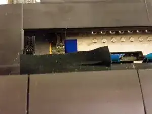
Remove the tape covering the touchpad connector.
-
Use any long tool to pull gently upwards on the touchpad cable locking connector, then pull up on the cable.
-
Repeat for the next four connectors.
-
Pull upwards on the palmrest.
-
-
-
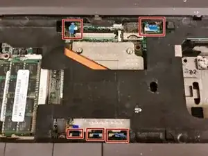
Remove the three small screws from the USB board, and remove the USB board.
-
Remove the two small screws from the VGA board.
-
Remove the one long screw from the VGA board, and remove the VGA board. This is a tight fit and may require a little jiggling to remove/replace.
-
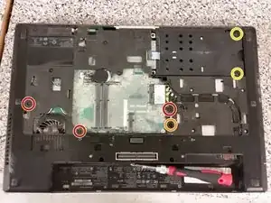
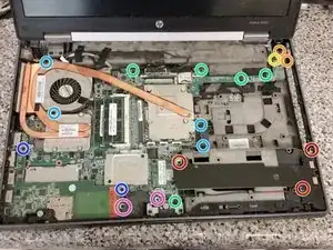
Remove the five small screws from the motherboard.
-
Remove the four long screws from the motherboard/CPU cooler.
-
Remove the two short screws from the DP/USB/Firewire board.
-
Remove the two mid-length screws from the left speaker, and disconnect the speaker connector from the motherboard.
-
-
-
Remove the short screw securing the LCD assembly to the base.
-
Remove the three long screws securing the LCD assembly to the base.
-
Flip the laptop over and remove the wireless antennas, pulling them from their clips.
-
Also remove the modem port plug from the modem card, and remove the cables from their clips.
-
Remove the four silver screws from the back of the laptop securing the LCD assembly to the base. Keep these screws separate from the other ones.
-
Remove four more black screws securing the LCD assembly to the base.
-
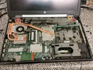
Remove the LCD cables and LCD assembly from the motherboard.
-
-
-
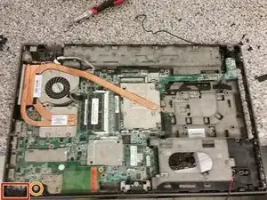
Here on the left-front, there is some rubber. Take the rubber out to reveal a small screw.
-
Unscrew one screen latch screw.
-
Lift the SD Reader board at 45-degree angle, and pull it out.
-
-
-
Underneath where the SD Reader board was, there will be one short screw holding the motherboard.
-
There will also be a longer screw.
-
There will be a short cable attached to the bottom of the motherboard. Don't tug on the motherboard just yet, just lift it slowly and carefully. Be sure to remove that cable.
-
At last, you are done!
-

To reassemble your device, follow these instructions in reverse order.