Einleitung
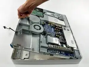
Remove your midplane assembly to gain access to your display and front bezel.
Ersatzteile
-
-
Lay the iMac display-side down on a flat surface.
-
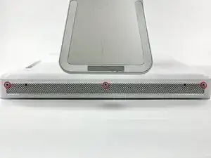
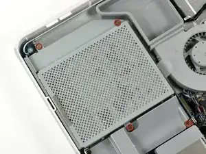
Loosen the three Phillips screws securing the rear panel to the iMac.
-
-
-
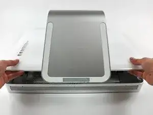
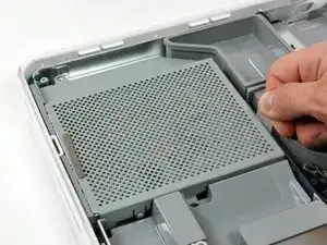
Lift the rear panel slightly near the bottom of the iMac.
-
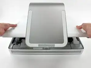
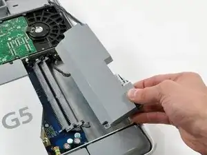
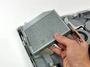
Pull the rear panel toward yourself and remove it from the iMac.
-
-
-
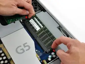
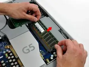
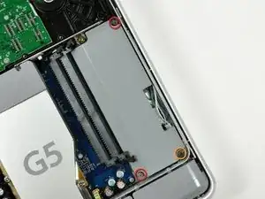
Rotate each of the two RAM retaining arms away from the RAM chip.
-
Pull the RAM chip straight away from its socket.
-
-
-
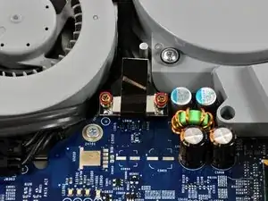
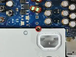
Remove the following three screws securing the inverter to the chassis:
-
Two 7.9 mm Phillips.
-
One 26 mm Phillips.
-
-
-
Disconnect the large inverter cable connector from the inverter by pulling straight away from its socket.
-
-
-
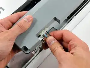
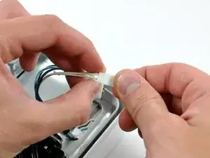
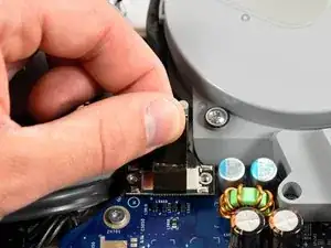
Disconnect the small inverter cable connector by pulling it straight away from its socket.
-
-
-
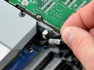
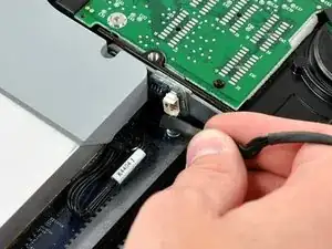
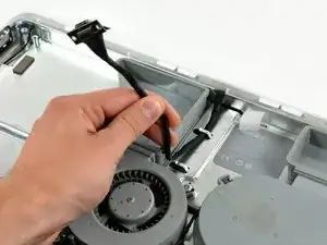
Disconnect the hard drive thermal sensor cable from the thermal sensor board on the hard drive bracket by pulling the cable away from the heat sink.
-
-
-
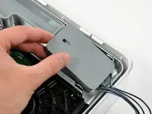
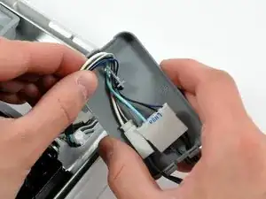
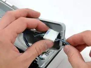
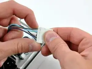
Remove the inverter cables from the inverter cable cover, and disconnect both connectors.
-
-
-
Pull the optical drive up by its white pull tab to disconnect it from the logic board.
-
Lift the free end of the optical drive slightly, then pull it away from the edge of the rear case to clear the two plastic positioning pins.
-
Lift the optical drive out of your iMac.
-
-
-
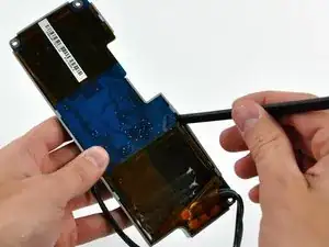
Remove the two 7.3 mm shouldered Phillips screws securing the display cable connector to the logic board.
-
-
-
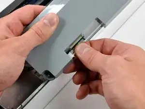
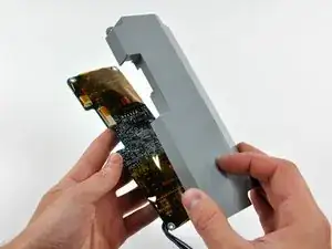
Pull the display data cable up off the logic board by its black pull tab.
-
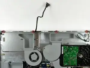
De-route the display cable from the two aluminum fingers in the mid-plane.
-
To reassemble your device, follow these instructions in reverse order.

Some models (with light sensor) have only the two outboard screws.
Robert Huber -